Not something I did to save money. That would have led to a different system.
The climate crisis is the existential threat to the planet and all the creatures that live here. If we are to avert the worst of its effects, we must as a species make changes to our lifestyles. Unfortunately, it is human nature to embrace comfortable habits, to subconsciously disconnect the link between those behaviors and global warming.
For much of the growing human population, climate change is not even a thing.
However pessimistic I may be about global warming, I still feel compelled to do my part to contribute to the solution.
In this blog post, I will lay out my solar-system goals, the institutional constraints I’ve encountered, and — the main part — the process of installing the system. I’ll also present its preliminary performance, looking forward to a series of YouTube videos documenting how well the system fared in meeting all of my power needs — into the short, sometimes gray days of winter.
Goals
After almost ten years of preparations and planning, I now have a solar system installed at my house. It’s been exactly ten weeks since I signed the contract for the system install, no doubt reflecting the complexity of the project.
My overall goal has been to minimize my carbon footprint, to have a system that would power my all-electric house and electric car — not just during sunny summer days, but year-round, day and night. No fossil fuels. No dirty grid power.
Facilitating that goal was moving to San Diego county where the sun is intense and shines almost every day. I bought a house with a south-facing roof angled at 22˚ (almost ideal). To minimize energy use, I upgraded the substandard insulation in the attic and walls, and replaced the single-glazed windows with efficient double-glazed units. I removed the fireplace and chimney — a big hole in the house (and of course burning wood releases carbon dioxide, and pollutes the air). I replaced the gas furnace with an efficient heat-pump, well-suited to the moderate climate. I replaced the gas water heater, clothes dryer, and kitchen appliances with electric units. And I replaced my fossil-fueled car with a Tesla Model Y, which I’ve been driving for two years.
Institutional Constraints, or The Politics of Solar
Southern California is one of the hotspots in the U.S. for residential solar system installations, due to abundant year-round sunshine and ridiculously high electricity rates. While the average electricity rate in the country is 13.7¢/kilowatt-hour, here in San Diego the lowest off-peak rate is around 22¢/kWh, rising to over 60¢/kWh peak rate.
Our local investor-owned utility monopoly has demonstrated antagonism toward residential solar owners, and continues to invest in gas pipelines and a new gas-fired power plant. They complain that residential solar owners produce excess power during mid-day when demand is low (sent to the grid pursuant to a net energy metering agreement), but produce little power during the peak demand period (late-afternoon into evening). The utility then has to dispose of that excess mid-day power, often at no profit. The obvious solution to this imbalance would be to install large-scale battery facilities (as other utilities have done) to store mid-day renewable power for release during high demand periods. But no. Instead, they want solar customers to buy their own batteries.
Last year the utility tried to raise the monthly minimum charge from $10/month to $40/month in a bid to generate more revenue from all those free-loading residential solar owners. The California Public Utility Commission shot that down. A few months ago they submitted another proposal, that among other things, would have charged residential solar owners $8/month for every kW their solar system was rated for. For me, it would have been an almost $80/month charge—using no grid power. The proposal generated tens-of-thousands of outraged complaints, and rare involvement from the Governor, who suggested it needed changes.
The proposal was withdrawn, but what next?
My “Biggie” Solar-plus-Battery Installation
Over the period of a couple of years, I spoke to the salespersons of five major solar installers. None were willing to install an off-grid system (a few saying they had an agreement with the utility not to), and neither would they configure a system that would back up the whole house in the event of a grid outage. That even though they had schematics showing whole-house backup systems—apparently installed in other locales.
They wanted to install the hardware for “critical loads backup.” In other words, if the grid went down, your solar-plus-battery system would provide power to the refrigerator, lights, and other “critical” circuits.
For most people, that might be fine. But if you wanted your system to be able to power your whole house — to essentially function off-grid, that’s not acceptable.
Finally, a friend recommended a small contractor who was happy to accommodate my (after years of research) rather specific requirements, rather than doing a quick cookie-cutter installation. He worked with me to configure a whole-house backup system, put the batteries in the garage at the opposite end of my house from the main electrical panel, and put the control electronics inside the house (versus outside on a western-facing stucco wall that gets extremely hot in the afternoons).
I had already decided to use Enphase microinverters, and while initially I thought I would use Tesla PowerWall batteries, I discovered the new Enphase batteries had distinct advantages. They used a different version of the same microinverters used with the panels, they used lithium iron phosphate cells (which liked to be charged to 100%—so long life). The batteries only needed to be passively cooled (PowerWalls were more complex with fans and liquid cooling). Perhaps most important, Enphase provided a complete integrated system controller.
I wanted BIG — a system that would not just power my house during long sunny summer days, but also during those short, occasionally gray winter days, and nights. I wanted to max out my south-facing roof with solar panels.
I had wanted LG panels, but unfortunately LG had shut down their solar panel business three weeks earlier. The contractor used Q Cell panels, which I discovered were rated in the top five. Good enough.
The maximum Enphase system battery capacity is 40 kWh, equivalent to three Tesla PowerWalls. Enphase offers 3.3 kWh batteries, and 10 kWh batteries (which combine three of the smaller batteries). So my system uses four of the 10 kWh batteries. They are delivered as twelve of the 3.3 kWh batteries, plus mounting brackets and covers to combine three of them into each of the 10 kWh units. A lot of boxes in my garage.
Because my system was an early battery installation of this size, the contractor hired a professional videographer to shoot a publicity/information video about the Enphase batteries. SolHome
My roof was big enough for 24 panels, each rated for 400 watts maximum output, for a rated system output of 9.6 kW. Most of the time the output will be less than that. For my electricity usage, that many panels would be overkill — if I was sizing the system for perfect sunny summer days, when power output will be prodigious. I was thinking about those overcast winter days, when panel output will be much less. So now the question is will they be enough?
The panels are fastened to extruded aluminum rails, which are supported by pads that slide under the shingles and are screwed into the roof trusses/rafters.
The vertical rail support is called a bunny (looks like ears).
Each panel gets its own microinverter (in my case the Enphase IQ8+ model), which converts the direct current (DC) from the panel to 240-volt alternating current (AC) compatible with the house’s electrical service.
Solar systems can also use larger “string inverters” which are located down with the main electrical panels and convert DC to AC for a “string” or group of panels. With string inverters, if one panel’s output drops, due to shading or whatever, the total output for that string of panels drops. With microinverters, if one panel is shaded, you only lose power from that one panel.

Enphase makes several series of inverters; the newest, most advanced is the IQ8. That’s what I wanted. But there are several IQ8 models, with increasing power output capabilities. I ended up picking the IQ8+ version, even though its maximum power output is just 300 watts. Why would I use a 300-watt microinverter with a 400-watt panel? It’s a decision I made early on, before I was aware of the maximum power output, and one I still revisit. A significantly more expensive IQ8A microinverter, rated for 350 watts, would have given me significantly more power under ideal conditions, but would that have made a difference in my overall system performance?
Enphase has published a white paper called “Why is my PV Module rating larger than my Inverter rating? (Mar 2022)”. Yes, why? The PV module rating is for ideal conditions, that are not realized for very much of the time, if at all, due to sub-optimal panel orientation, normal panel degradation, shading, dust, and heat. Still, producing more power than the microinverter can process results in “clipping,” basically throwing away power. But how much does this happen?
The Enphase paper includes simulations for various power modules and the different IQ8 inverter versions, in different U.S. cities (different latitudes and weather). For Los Angeles, the table gives an IQ8+ first year clipping loss of just 1.3%; after 25 years, during which the panel output will have slowly degraded, the total clipping loss would be less than a tenth of a percent. By comparison, clipping loss for the IQ8A during the first year would be 0%.
For Los Angeles, the IQ8+ used with my 24 modules will produce 17,304 kWh of electricity over the course of a year. If I had gone with the IQ8A microinverter, my system would have produced 17,684 kWh of energy. So, 380 kWh more. But how much power do I use in a year? From my electric bills, I used 6,775 kWh during the last year — just 40% of what my IQ8+ system can produce.
So maximum output isn’t likely that important, at least in my case (but may be in others). On sunny summer days I will be blasting out power, but what happens after I reach all my needs from just the panel output, and the batteries have charged to 100%? What happens to that excess power? Because I’m not participating in net metering, I can’t export my surplus power to the grid (and don’t want to). What happens is the System Controller and microinverters then start shutting down power output to match what I need at any moment. Maximum power potential becomes irrelevant.
The critical situation is — will I be producing enough power during overcast winter days, when panel output goes way down (how far down, I won’t know until next winter)? In that dim-sunlight situation, the IQ8+ microinverters will be able to process all the power the panels can output.
That said, if I had to do it over again, I might have chosen the IQ8A microinverters, simply because the added power makes me feel, well, more powerful! Over the next year or so, the data will suggest the logical best choice (but after a day of operation, the IQ8+ seems to be all I need).
Back to the microinverter inverter installation.
The inverters are mounted to the rails, and then the panel output wires are plugged into the inverters.
Here’s a photo of all the panels mounted on the roof (their output wires are collected into conduit and then routed through the roof, into the attic, and then down into a “Combiner” panel).
Batteries
Here are the batteries mounted to my garage wall (without covers), and wired into a circuit breaker box (so each 10 kWh battery can be separately shut off). The power output is combined and routed up into the attic; the conduit then runs to the other end of the house.
Each of the separate twelve batteries contains a bank of IQ8 microinverters, which converts incoming alternating current from the solar panels (not used directly for house needs) into direct current to charge the batteries. When the solar panel output is insufficient to satisfy the house’s electrical requirements, the batteries output direct current which the microinverters convert back to 240-volt alternating current (used by the house load center/breaker panel, which adjusts the power to either 120-volt or 240-volt to suit each circuit).
Here are the batteries with their covers in place.
Power Electronics
Once the panels and batteries were in place, the electronics to make everything work together were installed. Recalling the schematic from the first illustration, there was the existing outside combination meter and breaker panel, the new load center/breaker panel, a “Combiner” that collects all the solar panel outputs together, and a “System Controller” (a.k.a Smart Switch) that brings together all the power sources and routes it all to where it needs to go.
The existing grid power service entrance was a combination meter and breaker panel (“load center”), located on the outside of the house. All of the house circuits in this (cramped) panel got their power from just one source — the grid. In the new system, power comes from the solar panels, or the storage batteries, or the grid, or some combination of those. The new System Controller prioritizes power routing and sends it to a spiffy new separate load center/breaker panel, where it gets distributed to the electrical circuits in the house.
So now the power from the grid (if used at all) just needs to go through a meter before then being routed into the System Controller. A small meter box would be the best solution, but taking out the old panel and replacing it with a simpler meter box brings on a host of onerous and expensive county requirements. So all the old breakers were removed, and left well enough alone.
All the new breakers (since this is a whole-house backup system) went into a separate new load center. Since all the circuit wires had to be moved to this new panel (most coming down from the attic), it was advantageous to keep it as close as possible to the old panel. Also, it needed to be outside due to local ordinances mandating ready access for the fire department. Old panel and new panel:

I wanted the “Combiner” and the “System Controller” to be inside, away from the intense afternoon heat (to protect sensitive electronics), and the best place would be on the inside wall opposite the two breaker panels. There were lots of connections among all those panels, passing through the wall, so off with the drywall! (By contract, I was responsible for the stucco, drywall, and carpentry work.)
Further, I needed to make structural changes inside the wall to enable proper mounting. Also, I had doubled the wall thickness behind the existing panel long ago for insulation purposes, and I needed to extend that doubling behind the new panel. So:
The head of the company, his chief solar technician and I had a couple of meetings to work out where everything would go. After the initial meeting, I marked with tape the outlines of where I thought the Combiner and System Controller should go, to assist with working out the installation details.

I carefully removed the drywall in pieces that would facilitate the installation of the new components (and minimize buying and cutting new drywall).
At this point, it was important that the next steps in making all the new connections be made as efficiently as possible, because the first step was to move the circuit cables/wires from the old panel to the new one. To do that, we had to cut off power to the whole house, and this was not something I wanted to stretch over days. So planning each step ahead of time was critical, since mounting the Combiner and System Controller on the wall precluded any further access to the wiring behind the drywall.
The circuits were connected into the new-fashioned Leviton load center (breaker panel).
Here’s the Combiner (top) and the System Controller opened up.
This photo (below) of the inside of the Combiner shows the “Gateway” (aka Envoy) circuit board. This is the unit that reports how everything is doing, and sends it to Enphase and the customer’s app to show the flow of power and energy usage, etc.
The various components of the system all talk to each other. The health and performance of every individual solar panel is reported. This information will be critical in evaluating how well the system meets my goal of powering my whole house (and car).
Here are the two boxes with their inner doors closed, still allowing access to critical system circuit breakers and diagnostic lights. The little blue box transmits over wi-fi.
With those boxes installed, I started rehabilitating the drywall.
All pretty.
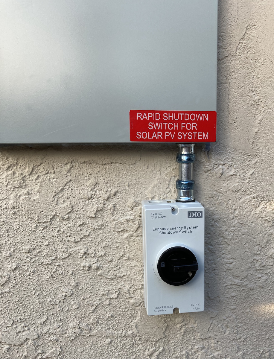
A new county ordnance required the addition of an outside switch that shuts down power from the solar panels and the batteries. There are already accessible main breaker switches to shut grid power off, and to shut power off to all regular house circuits.
And the warning labels for interested passersby:
So this is how the new inside electronics boxes fit into my pottery studio.

At this point, the equipment has all been installed, but the system has not been configured and enabled —a process called “commissioning.” There are many variations of solar systems — with batteries and panels, with panels alone, and with batteries alone. There are whole-house backup systems, and critical loads backup systems.
In some areas, residential solar owners can sign up for “net metering” (more properly “net energy metering” — NEM), whereby the utility company gives credits to customers who export surplus solar power to the grid. These credits can be used to offset power the customer uses from the grid when their solar is not making enough (or any) power.
If you don’t sign up for net metering, you can’t export surplus power to the grid. I’m not going with net metering, because it comes with problematic strings attached, and I’m not planning to use any grid power, so credits would be of little value.
So the commissioning process includes making sure my system does not send power to the grid. Another facet is telling the system how to use the batteries. I want to use them for self-consumption, to maximize my use of my own electricity production—meaning draw down the batteries (to 10% in my case) before pulling grid power (if the grid is down, the batteries will discharge to below 10%). One could also configure them to stay charged to 100%, so that in areas where grid outages are common, the batteries would be ready to take over with a full charge.
The county inspected the completed install—a quick painless event ending with a pass.
System Performance
By morning, I was able to see what my system was doing using the Enphase app. There is a real-time animated graphic for grid, panel, battery and consumption power flow.

Just during the first day, I noticed a few interesting things.

The first thing I noticed in the morning was the energy usage spike for the water heater (after taking a shower). Because the batteries were still in their first-24-hour backup mode charging up to 100%, the energy for the water heater spike (at 6 a.m.) came from the grid. On the chart above, black bars are energy from the grid, and the orange bars below the line are energy consumed.
Second, the blue bars above the line represent energy produced by the solar panels. Notice it started low after 6 a.m. (hazy morning sky), and then energy production rapidly increased before 9 a.m. as the haze burned off. Then there was a steadier climb as the sun continued to rise, with the power peaking after 10 a.m. to near the maximum rated microinverter output for the 24 panels.
The batteries were soaking up almost all of this power (green bars below the line). Then as the twelve individual batteries approached 100% charge, the system started cutting the solar panel output dramatically to match the declining charge rate.
Third, at this point I was losing a lot of power generation potential, so I turned on my car charger, first at a 12-amp rate, and then up to 16-amps as I saw there was still plenty of power available from the panels. You can see this as the much longer orange bars below the line (two bars at 12-amps, and then longer ones at the 16-amp charging rate).
Fourth, since there was still untapped solar panel power to be had (sun still high), I turned down the thermostat a degree or two to start the air conditioner. Clearly, not as much power needed as the car charger, but the panel output increased to match.
And by 11:15 a.m. the batteries were close to 100%, and so were barely absorbing any power from the panels. So certainly during this cloudless summer day, the system was capable of producing a significant surplus of energy.
After about 3:00 p.m., when the car was finishing charging and the air conditioner was shutting down, it looked like the solar panel output was ramping down, as expected. The consumption ramped down to match, but it was not clear to me what power was being used. At about 4:30, power use and generation both dropped to a small figure, consistent with my usage.
Overnight the batteries supplied the house’s modest power needs, and after feeding the morning water heater spike, the batteries’ charge had dropped to 88%. As the sun started to rise, panel output began to increase, and started to charge the batteries. By around 9:30, the batteries were back up to 100% and the microinverters began “active power curtailment,” that is, limiting the power produced by the solar system to match the modest consumption.

With the car and house batteries fully charged yesterday, there would be only modest power needs until late afternoon, when the air conditioning kicks in, but the A/C actually doesn’t draw much power. Do I need the grid? Not today! What I need now is an overcast day, one of the situations I will be studying in the future.
Looking Ahead - Energy versus Power
I already mentioned that my energy usage for the last year was a fraction of the total annual energy production the system is theoretically capable of generating.
But energy is not the whole story. You might produce as much energy as you use during a given hour (or day), but if you need more power at any one moment than you are producing, your system fails.
So power is just as important as energy, if not more so. Power is the instantaneous rate of energy use, expressed as watts, or kilowatts (kW). For electricity, power is volts times amps. In the U.S., voltage is a constant, either 120 volts, or 240 volts for larger power uses (oven, water heater, etc.). So current (expressed as amps) becomes the variable. If electricity was water, volts would be pressure, and current/amps would be volume flow.
I’ve been living with less than 100 amps for years, and my new load center has a 125-amp rating. But can my solar plus battery system even output that much?
Well, no. My four big batteries are each limited by a 20-amp circuit breaker, which combined are limited by an 80-amp breaker. But each battery’s rated continuous output current is 16 amps, with a peak (< 10 seconds) current of 24.6 amps. So the contribution from the batteries would be a maximum of 64 amps, with short output surges possible up to 80 amps.
Each solar panel’s power output is limited by the microinverter to a maximum of 300 watts. At 240-volts AC, that translates to 1.25 amps per panel, or 30 amps total — maximum. By comparison, I charge my car at a relatively low rate of 16 amps (@ 240 volts).
So — about 94 amps continuous, maximum, solar panels plus batteries. And after looking at my first day performance, it’s more than enough.
But gray days? I can control my electricity usage by, for example, choosing when and how often to charge my car. Besides storing energy for use during the night, the batteries also play a big role in smoothing out power usage — supplementing panel production when demand is high and absorbing panel energy when loads are low.
I can also boost power (and energy) if needed, by adding another eight solar panels to my garage roof; the install has been pre-wired for that possibility. That would add as much as another 10 amps, or 2.4 kW maximum power — less on overcast days, but certainly a nice increase if juggling power use is not enough.
I am going to document the performance of the new system over the next year (or so), and make YouTube videos presenting those findings every couple of months. Here is the first: Going Off-Grid