Every place I've ever lived has been designed for that "average American family," with lots of bedrooms, living room, dining room, family room, etc. The problem was that I was a single person, not an average family. I needed space, but for hobbies, not people. And because I'm over 6'2", bending over to use sinks designed for children was a constant frustration. Over the years, I collected a list of things I would change if I could have my dream house. As I approached retirement, I realized time was running out for that house; it was now or never.
Dreams are not always perfect, however. I could never afford my dream house, a spacious Southern California home overlooking the Pacific Ocean. But I could afford a modest ranch house, with a 20-mile drive to the beach. It was a very long way from perfect, but it had potential.
This blog documents the process of turning that small average house into something that matches my lifestyle. It will be as close to my dream house as I can make it. I'm doing all the work myself to stretch my resources. By not hiring contractors, I can afford high quality materials, and I'll know the job is always done right. The remodeling will be my primary avocation for a few years, even as I try to fit in my writing and other hobbies.
It promises to be an interesting journey, and a challenging one!
Saturday, October 28, 2017
Test Drawers
Drawers for my waterbed base. I needed five on each side. I installed the drawer slides during the assembly process for the bed because it would be very difficult to do it after the fact. So the slides were ready.
Not a very exciting post, this, so unless you're actually thinking about building some drawers and are not too clear about the process, I suggest clicking through the photos and moving on to something more interesting. (Next post — kitchen countertop — much better.)
I call this a "bonus" project because the work was done ad hoc in bits a pieces while working on other more "substantial" projects. And not in an organized fashion. For example, I cut out pieces from plywood remnants that were lying around that happened to be a size that matched what I was making. So if the drawer fronts were 7" wide and there was a piece of 3/4" plywood sitting there that was 7.5 inches wide, I would rip it to the proper width, and then cut as many drawer fronts as I could make from that one piece.
For the sides, I ended up with enough for all ten drawers. For another part, enough for three, and others, enough for four, or five. Rather haphazard.
And the whole assembly process was an experiment, a development process — a test.
And so it came to pass that I ended up with three drawers. Three imperfect drawers, but nobody will know except me.
So I started with the sides. 22" deep sides (front to back). Twenty identical pieces, and they sat in a pile for awhile:
After awhile I measured the width of the openings for all ten drawers (five on each side of the bed). They were not all precisely the same, which is important, because for the drawer slides to work properly (or at all), the drawer width had to be exact. The width of the drawer had to match the distance between the right and left slides. A little play allowed. No wider at all, but perhaps as much as a sixteenth less, so little slop. Better to be exact. Drawers slides are a half-inch thick, so the drawer width should be exactly one inch less that the opening.
I measured the openings, and they were very close to nominal (and each other), but slightly different. So the fronts and backs for the drawer carcass had to be individually measured and cut. (If you're mass producing drawers, the furniture and drawers are likely machine cut (CNC), and can be made all the same.)
I'm making the drawers for the bed base from 1/2" cabinet-grade plywood, because it's straight and doesn't tend to warp or cup. It's also affordable compared to solid half-inch thick maple or similar wood, especially for wider widths. These drawers are 7" high.
I'm also not using dovetail joints for these drawers. Cutting dovetail joints (with a router) in plywood would not likely be as clean as with solid wood, and for these drawers (holding clothes), the glued tongue and groove/dado joints I use for cabinet building will be plenty strong. I cover the edges of the plywood with maple trim where they could be seen. Not on the bottom, though — which shows how the drawers are assembled:
I initially intended to make the bottoms out of quarter-inch plywood, but saw a masonite-type material at Home Depot that was covered on one side by a white acrylic membrane. It makes for a nice drawer interior finish, and it's strong enough for clothing. I cut a quarter-inch slot in the sides, front, and back of the drawer to hold the bottom and glued it in place when I assembled the drawer. You can see the end of the groove in the photo above.
You can also see the part of the drawer slide that is screwed to the drawer. Three screws. The slide is positioned using a jig — just a piece of wood ripped to a width that positions the bottom of the drawer just above the bottom of the drawer opening. Clamp it to the drawer and hold the metal slide against it while screwing it in. I actually used a awl to mark the holes, then drilled, then screwed.
The drawer box is glued with clamps, making sure it's square. The bottom helps it keep it square, assuming minimal slop, but it pays to check anyway. Then I glued maple trim to cover the unsightly plywood edges (also to stiffen the sides).
I like inset drawers (as opposed to drawer where the front overlaps the cabinet edges). Inset drawer fronts have to be precise, with an even gap around their edges. This is easier to do if a separate "front" is made and fastened to the drawer after it is installed. Wait for it.
For the purposes of my bed drawers, I'm making pretty ordinary fronts. Basically, a piece of painted plywood, with maple edges — to wit:
These are put together with biscuits to keep the edges even with the 3/4" plywood, then glued together.
I like wire pulls, and use mostly the 3" wide variety.
A jig is really required to drill the holes in the front of the drawer to fasten the pulls. The simple jig ensures that the two holes are exactly 3" apart, and will place the pull in the center of the drawer (right-left), and in this case, the same distance down from the top edge of the front. If you're doing a lot of drawers, you NEED a jig.
I used 3/4' plywood for the jig, thick enough to ensure the drill bit will be guided perpendicular to the drawer front (I drilled the guide holes in the jig using a drill press). The centerline of the jig is marked and matched to the center of the drawer (marked in pencil). You can also just glue on an end-stop instead of measuring the center, but I wanted to use this jig on drawers of different widths. Clamp the jig to the drawer front.
And drill the two holes in the drawer front using the guide holes in the jig.
Remembering that my drawer openings were not precisely the same width, and that the pieces of plywood for the fronts were measured and cut individually for each drawer opening, it's now time to fasten each drawer front to its matching drawer. First, position the drawer front in the opening, holding it against the drawer (already installed on its slides). Then for these inset drawers, shim the front so there is an equal gap all around the edges. I used pieces of cereal box cardboard for shims.
The photo above also shows one of the drawer carcasses (on the right) installed on its slides. You can see the maple edging—thin on the top of the front and the back, and a thicker wrap-over piece for the top of the sides — looks nice and makes the half-inch sides a lot stiffer.
I had initially intended to use hot glue to temporarily fasten the front to its drawer until screws could be put in, but tried a quicker method that worked for me. Once shimmed, I held the front against the drawer and then drilled into the drawer through the holes in the drawer front (holes sized for the screws for the pulls). I then removed the front and opened the drawer, and inserted the screws for the pull through the holes on the inside of the drawer, and screwed them into the pull, held on the outside of the drawer front. Then I rechecked to make sure the gaps were good. Then I drilled and fastened four screws from the inside of the drawer into the drawer front. From the inside:
One drawer partly open (these have 22" full-extension drawer slides):
And the three test drawers. Done.
Now just another seven side drawers to go, and a long one for the foot of the bed. And drawers for the kitchen, laundry room, pottery studio, workshop, two bathrooms, . . . Another 150 drawers, more or less. Some of them basic, and many of them fancy with dovetail joints, solid sides, and very nice fronts (spalted maple, mahogany, birdseye maple, cherry).
Planning to build drawers this winter. Lots.
Sunday, October 22, 2017
Tile on Front Porch
That plan changed when I discovered I did not have enough of the large squares (but had lots of the mosaic tile). So I experimented, putting down tile in different patterns dry.
I would try to put down as much of the tile as possible without cutting, but needed to cut the large squares to cover the front and sides of the slab. I used my wet, sliding-table tile saw to do that (and later, to cut the small tile when I reached the front of the house). The basic process was to mortar the border and let that dry, and then fill in the field with the small mosaic tile, which came in foot square sheets (bonded to a flexible mesh backing). There was some slight variation in the sheets, and spacing of individual tiles; the trick was to try to even them out as much as possible.
I used a notched trowel to spread the thinset mortar. For the large tile, I also skim-coated the back of the tile, since none of them were really flat (this being a "natural" stone product.
The edge of the porch tile was sharp, so I beveled the hard corner with a diamond grinder. Perhaps not pretty, but nobody is going to inspect too closely.
Here is a photo of the tile all down. Because of the "drift" of the sheets across the width of the porch, and my inability to adjust the spacing of the tile within individual sheets, the gaps ended up being too big as I closed in on the other side. So I then pulled the individual small mosaic tiles off the backing, and placed them one at a time, which gave me more control of the spacing. Probably should have done that sooner, but then again, normal people aren't going to get down and inspect the tile spacing (unless obsessive/compulsive).
When the mortar was sufficiently cured, it was time to grout. The question was then — what color? I thought a medium gray — something that matched the average color of the tile. I had half a bag of "new taupe," and the little color label looked like a medium gray, maybe with a little earth tone. At that stage, I thought I would seal the stone tile, which will bring out its deep earthy colors, so I thought the "new taupe" would do.
The basic procedure for grouting is to mix the grout with water, wait ten minutes, mix the stiffened mixture some more (which makes it more compliant and smooth), then spread it and force it into the gaps with a grout float held at a 45˚ angle, more or less:
When that is done, scrape off the excess with the float held closer to 90˚ to the surface. With regular smooth ceramic tile, that removes almost all the excess grout, but because the surface of this natural stone was rough, there was more grout left on the surface that needed cleaning off.
Cleaning the grout off the surface is done with buckets of water and special small-pore grout sponges. Submerge the sponge in the water, squeeze almost all the water out (you don't want water running into the grout that's in the gaps), and wipe over the surface. Clean the sponge in the bucket and repeat, again and again, until the surface is pretty clean. Then do the same thing with a bucket of clean water until there's no grout on the surface of the tile.
The grout tends to lighten as it dries out, over a period of days. Had I to do it over, I would have used a lighter, gray grout, but it looks fine, and the look will be different after sealing. In the meantime, this is it:
The empty square in the middle is for a decorative tile that I will make after my pottery studio becomes operational (a future post).
Concurrently with this work, I have been laboring diligently on the new kitchen countertop, but that's going to take another couple of weeks to complete (although good progress so far, just lots of steps). The next post, however, will be about my little bonus project — three test drawers for my platform bed (out of eleven).
Sunday, September 24, 2017
Concrete Work — Part 4
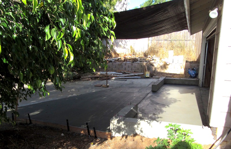
Well, just have to remove the 2x6 forms from the side of the driveway slab, and take the plastic sheet off after a couple more days (don't want the concrete to dry out before its initial cure).
At the end of the last post, I had removed the forms from the foundation (stem) wall, leaving trenches on both sides of the wall, and big piles of hard chunks of dirt and granular soil. The trenches needed to be filled in, and the piles of earth needed to be removed, to make the ground flat and level (more or less), roughly 4.5" to 5.5" below where the surface of the new slabs would be.
Unfortunately, the big chunks of hard soil were mixed in the piles of more granular soil, that could be shoveled into the trenches. It took a few days of separating out the chunks using a pitchfork, three-tined cultivator, and rake, and hauling them to piles in the back yard. The granular soil was then added to the low areas (and compacted), and dug out from the high areas. I also bought ten bags of sand to help with the leveling. Once that was under control, I started making the new forms, beginning with the simple form at the side of the new driveway where it met the yard.
That was the easy part. The more challenging form was that separating the level garage slab from the sloping driveway slab, the latter being a half-inch lower at the interface. I decided that a strong but thin piece of wood solidly attached to the concrete wall was needed. I ended up using a 3/4" thick piece of hard maple with a dado routed in the top edge to separate the two levels of concrete. I fastened it to the concrete wall with special concrete bolts (screwed into holes drilled in the concrete), supplemented by construction adhesive.
The maple will eventually rot, creating an expansion joint that can be filled with sand. Seemed like a waste of a good piece of maple, but the wood store had a big stack of it and it was on sale. (bought another piece for my kitchen countertop)
I also glued pieces of expansion joint to the front of the foundation wall that would be used as a guide to level the top of the concrete driveway. Here's what it looked like with a bit more leveling to do. I used a long straightedge to measure how big the gap was above the soil, adding or subtracting until arriving at a slab thickness of 4.5 to 5.5".
Then I placed the rebar and steel mesh — a lot in the the new extended garage slab, and little to none in the driveway slab (the rest of the existing driveway had no steel reinforcement). I drilled into the existing garage slab and epoxied four pieces of rebar into those holes, tying the new and old garage slabs together).
And then I took a breath, and waited. Saturday morning arrived to lightly organized chaos. No time for photos. The concrete truck arrived 30 minutes early, and my neighbor the concrete maestro had gone off on some errand, but he also showed up as I confided my anxiety to the personable truck driver, who conveyed the idea that all would be just fine. But my neighbor's son-in-law assistant was still missing. We forged ahead, I jumping from one task to the next — five things going on at once, concrete flowing out of that long chute, being shoveled and vibrated and shoved into place.
The assistant arrived and I focused on my task at hand, and then the next. After awhile, enough concrete had been dispensed, and the truck driver set about cleaning the concrete out of the chute. I guided where that could go, and then my prime responsibility — that would be writing checks.
The truck left and we continued to work. The assistant left and I became the new prime assistant. 9:30 a.m. to 3:30 p.m. Six hours and the job was done. No break for lunch. Concrete waits for no man.
Looked like this:
And this:
The concrete maestro does beautiful work. I was amazed there had been no disaster. I took another breath, ate a late lunch, and misted the concrete with water and covered it all with plastic to keep the moisture in until the concrete was cured.
Done.
Next project: finish the kitchen countertop. Then cover the newly poured front porch concrete with quartzite tile. Then pottery studio cabinets. Then drawers . . . Sigh.
Monday, September 11, 2017
Concrete Work - Part 3
So the construction of the wooden forms for the concrete went relatively quickly, if not straightforward. In my past, I've put forms together using special metal rods called "snap ties," which hold the two sides of the forms together at a constant separation, and resist the force of the wet concrete, which tries to push the form walls out (with considerable force). Snap ties look like this:
Neither Home Depot nor Lowe's carried them, and an internet search turned up no local sources. I did find out later, however, that a couple of concrete supply companies in the county have them (they apparently just don't have web sites with sophisticated search engines key words). So I improvised.
The lower trench I dug served as the form for the footings, and I built wooden forms that sat on a wider higher trench for the 24" high stem walls. Looked like this:
The lower section in the front wall is for the entrance to the garage, that is, where the garage door will go. To keep the wet concrete from the higher section of the wall flowing out the lower opening, I screwed a section of plywood on top of the opening after the lower section was filled with concrete and leveled. Here it is, ready to go.
The new walls are tied into the old garage concrete with sections of rebar epoxied into holes drilled into the existing concrete. I did the same thing with the porch slab.
The existing garage was built on a slab with no stem wall and no real footings, just a 6" wide by 6" high "curb" on top of the outside edge of the slab. So there was not much to tie into.
I put half-inch rebar in the forms — two rods running parallel inside the footings, and through the stem wall—one half-way up and two near the top. The anchor bolts for the bottom plate of the future stud wall were put in place in wooden braces that held the tops of the forms 8" apart:
You can see that I suspended the upper rebar from the wooden braces using nylon string. That worked, although if I had located the snap ties, I would have wired the rebar to the snap ties for a more solid connection. File that under — "if I had it to do over again."
The porch slab forms were more straightforward, and much quicker. They were just three 2x6s held in place with screws and steel stakes.
The future porch roof will be supported by two 4x6" posts at the front corners. The metal brackets that connect the posts to the slab are anchored by bolts cast into the concrete, and sitting on top of footings reinforced with steel rebar:
I hired a neighbor (who happens to be a concrete maestro) to take charge of the actual concrete pour. He brought along his son-in-law. And there was the concrete truck driver, and also the guy with the concrete pumper (concrete run through a big hose that could be more accurately placed inside the 8" wide forms, and could run over to the front porch — otherwise it would be pushing wheelbarrows back and forth). A big party. When wet concrete starts flowing, things happen quickly, and the more people on hand, the better. And that's a fact!
We filled up the footings first, and to give that concrete time to start to firm up (so pressure from concrete above would not force it out around the bottom of the forms), we moved over to the porch.
At that point, things became too hectic for me to take any more photos. I had calculated that we would need 3.35 cubic yards of concrete, and planned to add another 10% margin, which took the total to about 3.7 cubic yards. But you can only order concrete in half-yard increments, so we ordered 3.5 cubic yards, and that turned out to be not quite enough. I ended up hand-mixing three 60-pound bags of concrete to top off the forms. Another lesson for the "if I had it to do over again" file. But if everything was not optimal, the job got done, and no disasters.
That was Saturday morning. I started taking apart the form supports late Sunday, and removed the forms today (Monday).
And the porch:
So the next step is to backfill on both sides of the stem wall, to bring the level of the soil about 4" below the level of the new garage slab extension, and the new driveway directly in front of the extended garage. And then wire mesh and rebar for the new slab section. And then more concrete (in about two weeks).
And also back to the kitchen countertop project. I'll be buying more wood for that tomorrow.
Thursday, August 31, 2017
Concrete work & kitchen countertop — Part 2
While the digging was going on, I gravitated toward the much more pleasant countertop lamination. In the last post, I described the building of the flat and level glue-up frame. When that was done, I used the table saw to make strips out of 3/4" thick maple, cherry, and walnut boards, a little over one inch wide. These were turned on edge and arranged on my gluing frame.
Initially, I planned to do the whole countertop in maple, with just two walnut stripes. But then cherry came in, and I ended up with more strips of both walnut and cherry, so I just started arranging them until I ended up with something I thought I would not tire of over a decade or two.
I put the plywood undermount sink template (that I had made some time ago) on top of the strips so I could see where I didn't need wood, since the opening would be cut away when the countertop was all laminated. I am laminating the rough countertop to be thirteen feet long; the ends will be cut off square to a finished length of 12.5 feet. Ideally, I would have thirteen-foot long boards, but most of my strips are at most ten feet long, so by cutting them to skip the holes for the sink and the cooktop cutouts, one ten-foot board could span the whole thirteen-foot long countertop blank. (The pictures may explain that better.)
I am using a West System marine epoxy to laminate all the strips together, and will also put a couple of coats of epoxy on the finished countertop for complete waterproofing and stability. I'm using biscuits to align the strips during the gluing process (inserted into matching slots in adjacent strips). The working time for the two-part epoxy I was using is about 25 minutes. I set a kitchen timer so I would know when I had to start clamping the strips together (lest the epoxy start to set up, and everything thrown away). I managed to glue five strips together for the first batch, using twelve clamps.
For that first batch, I brushed the epoxy on each strip individually, and then mated it to the next strip, and so on. For the second batch, I arranged the strips against each other so I could brush the epoxy on a number of strips at the same time. Much faster.
Once the strips are glued together, they have to be planed flat and smooth, because of the glue runout and, well, because the strips are never going to be perfectly aligned. The kitchen countertop is 30" deep, while my thickness planer has a 12" width capacity. So I'm laminating the countertop in three sections, each between ten and eleven inches wide. Each section goes through the planer separately. Then the three sections will be carefully aligned and glued together. When the strips are clamped together, the epoxy gets squeezed out the top, but mostly out the bottom. I can scrape off the excess glue from the top before it hardens, but not from the bottom, so the first passes through the planer need to take the glue off the bottom.
Lots of space needed to get the long countertop section through the planer:
The second section is done pretty much the same as the first section, although the strips for the second section have to be clamped to the first section (but not glued yet), so the second section will be a perfect match to the first section. There are slight variations in the thickness of the strips which means that even if the first strip was perfectly straight, the last strip in a section will not be. Once the strips are glued together to form a 10" wide section, no amount of clamping will bend them to conform to the adjacent section, unless they were clamped together during the gluing process.
For the first section, I could use my six 12" clamps and my six 24" clamps. For the second 10" section, clamped to the first section, the 12" clamps would not work. So out came my 48" clamps to supplement my 24" clamps. Can't do a project like this without a lot of clamps.
Here's a look at the first two sections sitting side-by-side, after preliminary planing (all three sections will get a final fine planing to bring them to the same thickness before being glued together). The overall view, showing the cooktop cutout and the more distant sink cutout:
And a closer view. When coated with epoxy, the colors will be darker and more saturated, and the plan is to sand the epoxy to a satin finish.
As for the third section, I need to make the hour drive down to the hardwood store to buy more wood before countertop work resumes. Work has shifted to the concrete.
I finally finished digging the trench into the rock-hard ground. Again, the deeper trench is for the footings, and the forms for the 24" stem wall will sit, more or less, on the outer shallower trench.
The trenchworks had to be fairly precisely located, straight, square, and at the proper depth. To ensure the right depth for upper and lower trenches, I used a small laser level, along with a stick marked with the various depths. The laser level sat on the garage floor on a purpose-built box as a reference height.
And then I started building the stem wall forms, in sections, attaching them together, positioning, adjusting elevation, etc. At this point all the outer wall sections are in place. Now I need to start putting the rebar in, and then build and install the inner sections of the forms. Then tie them together, shim them level, stake them in place. Then concrete!